
In short
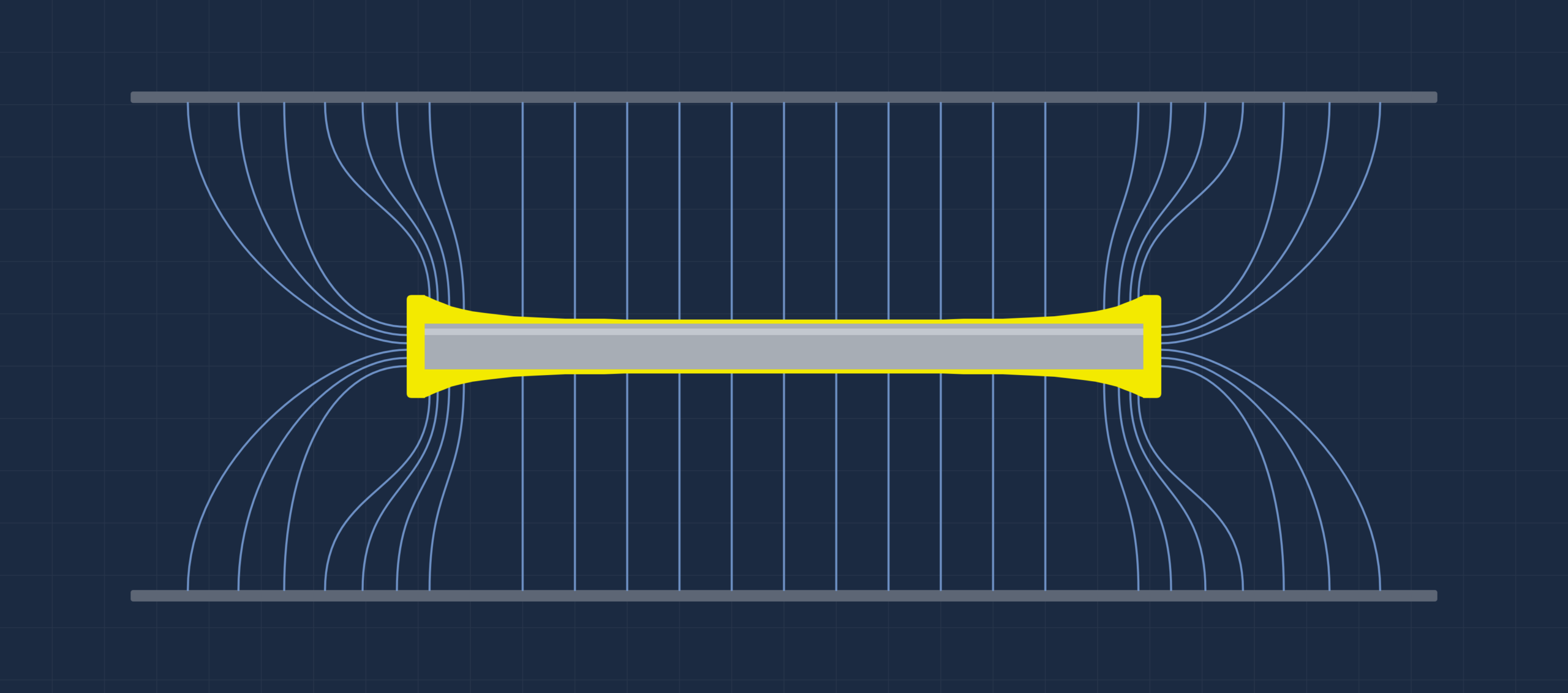
Long parts plate thicker at the ends than in the middle because the ends draw more current: the dog-bone effect. Hard chrome suffers worst, because its low cathode efficiency rises with current density. Shields, robbers and anode changes reduce it, but have to be set up part by part. Splitting the anodes into zones, each on its own FlexKraft 2 output, sets the current along the tank directly.
On this page
What the dog-bone effect is
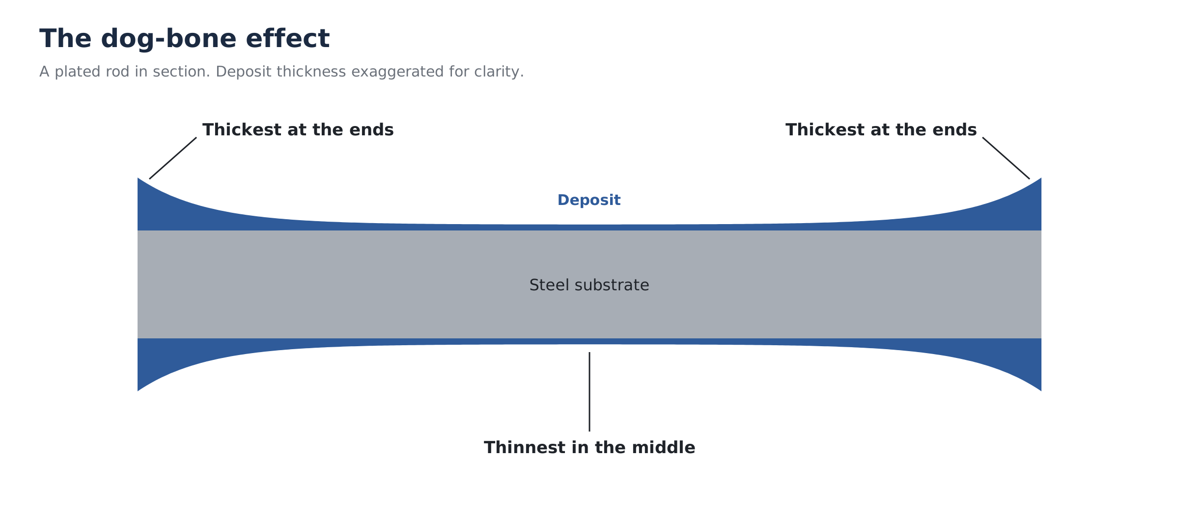
Plate a long shaft, a hydraulic rod or a flat bar, then measure the deposit from end to end. In most tanks it is thickest at the ends and edges and thinnest in the middle. Section the part and the profile looks like a dog bone: fat at both ends, thin through the waist. The same pattern appears in printed circuit boards, where copper builds up at the mouths of through-holes and thins towards the centre.
It matters most where thickness is specified and checked: hard chrome on rods and rolls, engineering nickel, and anything ground to size after plating. To bring the thin middle up to the minimum, the ends are over-plated, and that excess is paid for in metal, chemistry, power, tank time and grinding.
This article explains why current crowds onto edges and ends, why hard chrome suffers worst, what the usual fixes do, and how splitting a tank into separately powered zones tackles the problem at its source.
Why current crowds onto edges and ends
The short answer: a rectifier sets the total current, but the tank decides where it goes. Three effects decide it: the geometry of the tank and work, the electrochemistry at the surface, and, in chrome, how much of the current actually deposits metal.
Thickness follows current
Faraday’s law ties the metal deposited to the charge passed. At any point on the work, local thickness is proportional to local current density, multiplied by plating time and by the cathode efficiency (the fraction of current that deposits metal rather than doing something else). So a map of thickness across a part is, to a first approximation, a map of current density. Wherever current crowds, metal builds.
Local thickness ∝ local current density × plating time × cathode efficiency
Faraday’s law, applied point by point across the part
Primary distribution: geometry
Current travels through the solution along the electric field between anode and cathode, and every path has a resistance set by its length and the solution’s conductivity. The middle of a long part only draws current from the anode area directly opposite. An end or edge draws from the front, the sides and the space beyond the end of the part, along short paths, so field lines bunch onto it. The same logic gives high current density on corners and protrusions and low current density in recesses and bores.
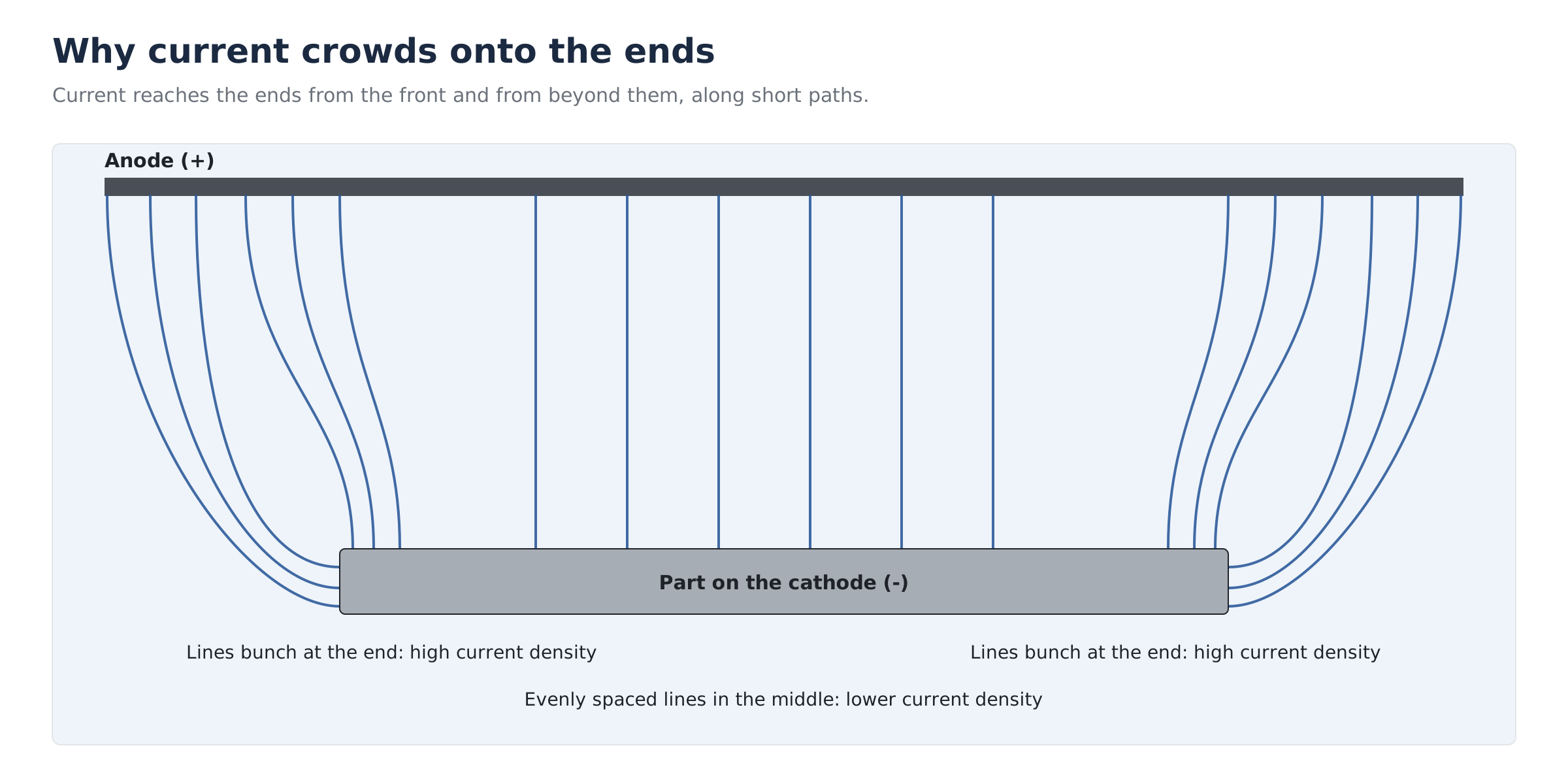
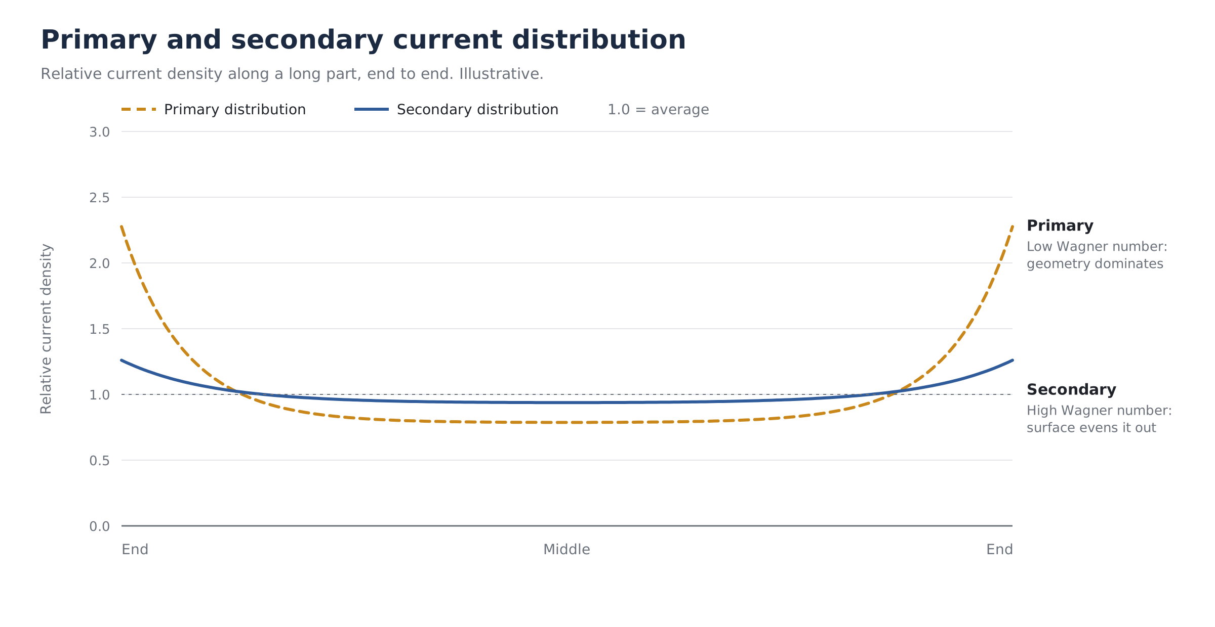
Electrochemists call this the primary current distribution: the distribution set purely by geometry and solution resistance, as if the electrode reactions offered no resistance of their own. It is the worst case, and on long parts it produces the dog bone.
Secondary distribution: the surface pushes back
Real electrode reactions need an overpotential, an extra voltage to drive them, and that overpotential rises as current density rises. A spot taking more than its share of current therefore has to work harder for each extra amp. In effect every point on the surface has its own small series resistance that evens out what geometry would do. The result, the secondary distribution, is always more uniform than the primary one.
How much it helps is captured by the Wagner number: the ratio of that surface (polarisation) resistance to the resistance of the solution across the size of the part. A high Wagner number means the surface resistance dominates and plating is even. A low one means geometry dominates. Because the part’s size sits in the denominator, the Wagner number falls as parts get longer, which is why dog-boning is chiefly a problem on long work. Solution conductivity, temperature and additives all shift it, and that is what a chemist means by a bath with good or poor throwing power.
At very high current densities a third effect joins in. Metal ions near the surface are used up faster than they can diffuse in, and edges burn: rough, powdery or nodular deposits, sometimes growing into trees.
Cathode efficiency: why hard chrome is worst
In Watts nickel or acid copper almost all of the cathode current deposits metal. Hexavalent hard chrome is different. Chromium is plated from chromic acid, and reducing Cr(VI) all the way to metal takes six electrons per atom and only happens with a catalyst, traditionally sulfate. Most of the current instead evolves hydrogen at the cathode, which is why chrome tanks gas so heavily and need strong extraction.
6
electrons to turn one Cr(VI) ion into chromium metal. Nickel needs 2.
10 to 13%
cathode efficiency of a plain sulfate hard chrome bath
22 to 26%
cathode efficiency of fluoride and organic catalyst baths
Typical hard chrome cathode efficiencies run from about 10 to 13% for a plain sulfate bath to the low to mid 20s for fluoride and organic catalyst baths. Crucially, efficiency rises with current density. So the ends of a part receive more current and also turn a bigger fraction of it into chromium. The thickness difference between ends and middle ends up larger than the current difference. Hard chrome also does not level, so roughness grows with thickness. Put together, these explain why hexavalent chrome has notoriously poor deposit distribution, and why controlling it with anodes and shields is regarded as a core hard chrome skill.
What it costs a plating shop
Specifications set a minimum thickness, so the job runs until the thinnest point reaches it. Everywhere else is over-plated, and the dog-bone profile decides by how much. Plating time is calculated on the low point, not the average, so the tank runs longer than the average thickness would need.
That excess has a cost on every load. It is metal and chemistry the customer does not pay for. It is rectifier energy, and in hard chrome that energy is mostly spent making hydrogen. It is tank time that could have run the next job. On parts ground to size afterwards, every extra micron on the ends is grinding time and wheel wear, and heavy edges can leave sharp ground edges that need blending.
In worse cases the ends fail outright. Burnt or nodular edges, out-of-tolerance threads and dimension rejects mean stripping and replating, which doubles the cost of the job and puts the delivery date at risk.
The usual fixes, and what they cost
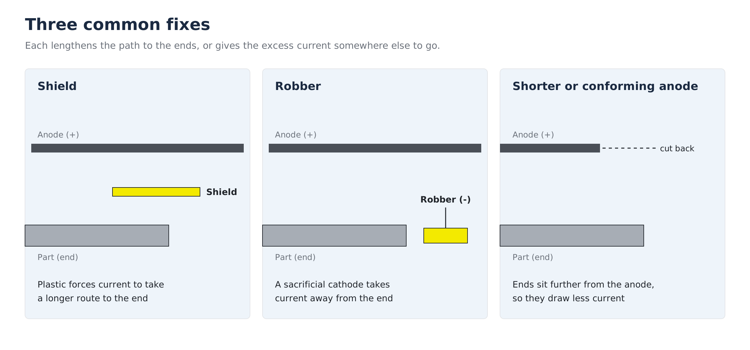
Every established method works on the same principle: make the path to the high current density areas longer or more resistive, or give the excess current somewhere else to go. Most shops use several together, and none is free.
| Method | How it works | Trade-off |
|---|---|---|
| Wider anode-to-cathode gap | Path lengths to ends and middle become more alike, so geometry matters less | Higher voltage and more heat for the same current; limited by tank size |
| Anodes shorter than the work | Current has further to travel to reach the ends, so less reaches them | Must be re-set for each part length |
| Conforming anodes | Anode follows the part shape at a constant gap | Made per part family; cost and storage |
| Shields and baffles | Non-conductive plastic forces current to take a longer route to edges and ends | Reusable and need no stripping, but need trial and error to position; a perforated shield loses its effect |
| Robbers or thieves | Sacrificial cathodes near the ends steal current from them | Very common in hard chrome; plate up, waste metal and current, and need stripping or replacing |
| Auxiliary anodes | Extra local anodes push current into bores and recesses | Fragile, fiddly to set up, a short-circuit risk |
| Bath chemistry | Higher-efficiency catalyst baths improve throwing power | In hard chrome, fluoride catalysts bring cathodic etch, extra masking and equipment attack |
| Lower current density | Reduces the burning and nodule risk at edges | Slower plating; in chrome, efficiency drops too |
| Pulse or periodic reverse | Reverse pulses dissolve some metal from high points | Proven in bright nickel, acid copper, zinc and tin; needs specialist power supplies and is less common in hard chrome |
| Part design | A radius on sharp edges removes the worst hot spots | Not in the plater’s control, and plating will round a sharp edge anyway |
All of these act through fixtures and tank layout. Each new part shape means another round of setting up anodes, shields and robbers, measuring, and adjusting. That is skilled, time-consuming work, and it depends on the people who know how each part was done last time.
Fixing it electrically: zoned current with FlexKraft 2
The fixes above all accept one rectifier feeding the whole tank and then reshape how its current spreads. The alternative is to stop relying on geometry and set the current in each part of the tank directly.
How zoning works
The anodes along a long tank are split into electrically separate sections, each fed from its own rectifier output. The work stays on a common cathode. Each output then holds its own current or voltage setpoint, so you decide how much current each length of the tank delivers. To flatten a dog bone, you turn the end zones down and run the middle at full. KraftPowercon’s own illustration uses settings of 20%, 70% and 100% from the ends inwards. Instead of fighting the primary distribution with plastic and scrap wire, you correct it at the source.
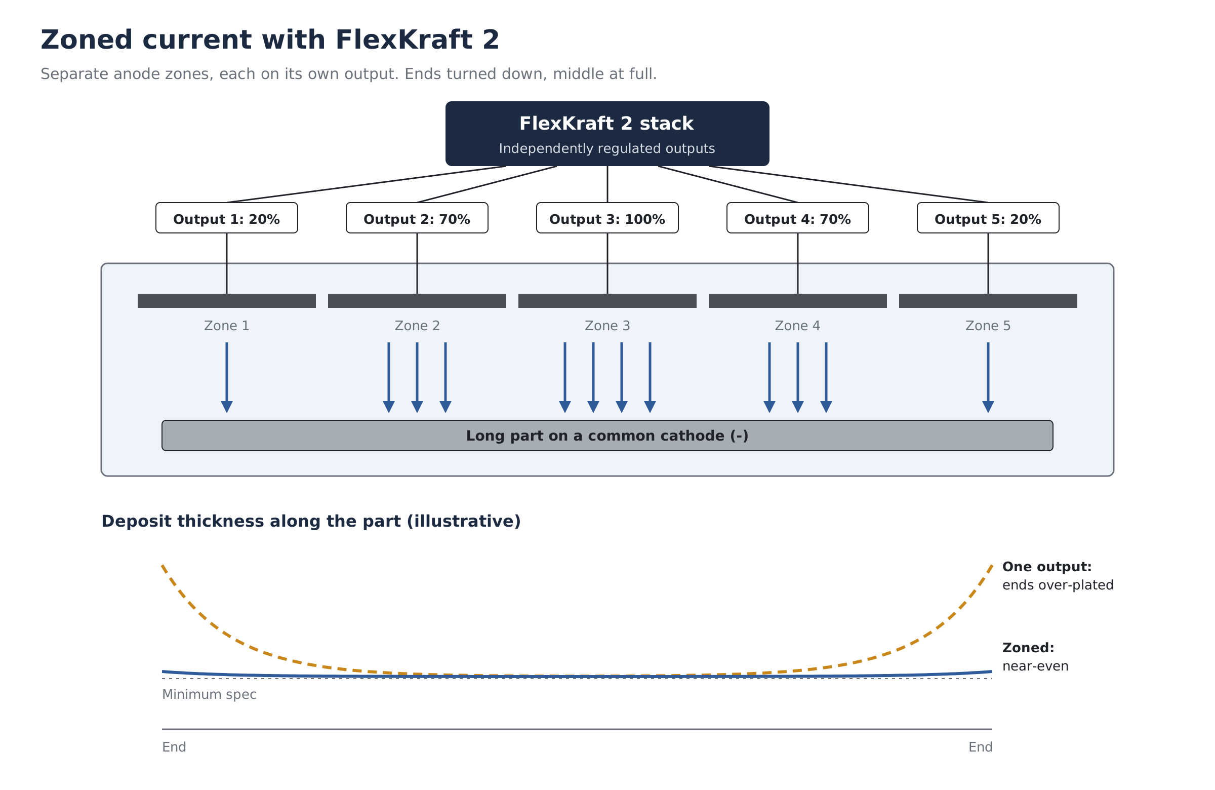
The same idea works the other way round for parallel loads. When several racks or parts share one rectifier, each draws a different current through its own contact resistance, so thickness varies part to part. Put each rack on its own output, with a common anode, and every rack receives the current set for it.
What FlexKraft 2 brings to it
FlexKraft 2, launched by KraftPowercon in November 2026, is built for this. Each power module divides into two half-modules of 334 to 400 A. Each half-module is individually addressed, measured and controlled over a digital CAN bus. One stack provides up to 20 independently regulated outputs under a single control module, and half-modules can be grouped into larger outputs where a zone needs more current. Each output runs in constant current or constant voltage, with setting resolution of 0.1 A and 0.01 V, about 1% setting accuracy and about 1% ripple.
Low ripple matters here as much as zoning. Ripple is the AC left riding on the DC output. Hard chrome needs smooth DC, and excess ripple brings burning, rough deposits and uneven thickness, which would undo the gains from zoning. Because every half-module reports its own current and voltage, a zone that drifts, perhaps from a corroded anode contact, shows up on the display rather than on the parts.
What zoning does not do
Zoning shapes the current along a tank and between parts. It does not change local geometry at a millimetre scale. A sharp external corner or a deep bore still has its own current distribution, and shields, auxiliary anodes or a radius on the drawing remain the answer there. In practice zoning replaces most of the tank-scale shielding and robbers on long work, and the remaining fixtures handle local detail.
Finding the right profile is a short exercise. Plate a test part, measure thickness along its length, adjust the zone setpoints and repeat. Once the profile is right, it can be stored and recalled for that part every time.
Controls that hold the profile
A zone profile is only useful if it is applied the same way on every load and every shift. That is a controls job, and Powerstax designs and builds control systems for FlexKraft 2 to suit how a shop works.
For a manual shop, that can be a simple panel: start and stop, a clear current setting for each zone, and an amp-hour count so the operator knows when the job is done. For a busier or more demanding line, it can be a PLC with a touchscreen. Each part number gets a recipe holding its zone currents, ramp-up, target amp-hours per zone and bath temperature. The operator selects the part and the line sets itself up.
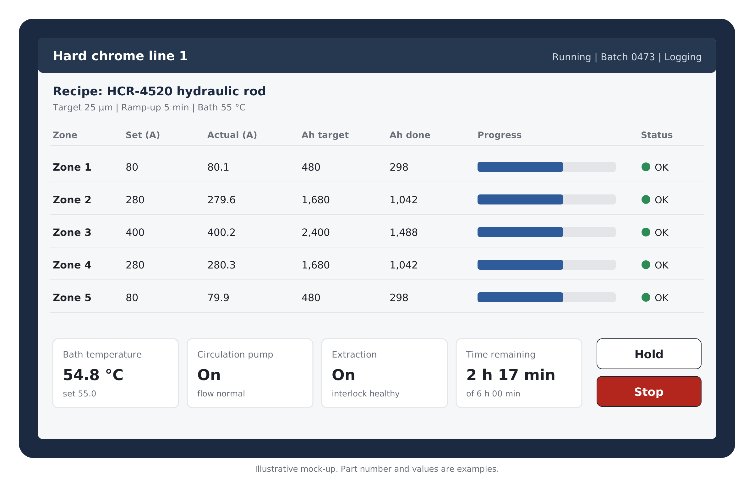
The same system can watch every zone during the run and raise an alarm if one drifts from its setpoint, control heaters and pumps, and log current, amp-hours and temperature for every batch. That record matters to aerospace and defence customers who ask for evidence of how their parts were plated. FlexKraft 2 offers analogue and digital interfaces, including Modbus RTU and Profibus DP, so it connects to the controls directly.
Questions platers ask about dog-boning
Why do the ends of my parts plate thicker than the middle?
The ends draw current from more directions and along shorter paths than the middle does, so their current density is higher, and thickness follows current density. The longer the part, the stronger the effect.
Why is edge build-up worse in hard chrome than in nickel?
Nickel deposits almost all of its current as metal. Hexavalent chrome turns most of its current into hydrogen, and its efficiency rises with current density, so high current density areas gain metal faster than their extra current alone would suggest.
What are robbers and thieves?
Sacrificial cathodes, often lengths of wire or scrap, placed close to edges and ends to take current away from them. They work and are widely used in hard chrome, but they plate up, waste metal and current, and need stripping or replacing.
Are shields better than robbers?
Shields are non-conductive plates that force current to take a longer route to the edges. They are reusable and need no stripping, and a narrow shield close to an edge can remove edge build-up. Getting the size and position right takes trial and error, and a shield with holes in it loses much of its effect.
Should sharp edges be radiused before chroming?
Where the drawing allows, yes. A sharp edge is a point of very high current density, and chrome will round it off anyway. If a sharp edge is needed in the finished part, it usually has to be ground after plating.
Will turning the current down fix it?
It helps. With typical electrode kinetics the Wagner number rises as average current density falls, so distribution improves, and the risk of burnt edges drops. The price is longer plating time, and in hard chrome lower efficiency as well.
How can I see my current distribution?
A rack distribution study: plate a typical load and measure thickness at set points along each part. A clamp meter on individual anode or rack leads shows how current divides. With FlexKraft 2, each output reports its own current, so the split is visible on every load.
Can a rectifier fix dog-boning on its own?
A single-output rectifier cannot: it sets the total current, and the tank decides where it goes. A multi-output rectifier feeding separate anode zones can correct the profile along a tank and between parts. Local features such as sharp corners and bores still need fixtures or design changes.
Does ripple make it worse?
It can. Ripple is the AC left on the DC output. Excess ripple brings burning, rough deposits and uneven thickness, and hard chrome is especially sensitive to it. A switch-mode rectifier with around 1% ripple removes that variable.
Talk to us about your plating line
Powerstax is KraftPowercon’s UK distributor and service centre. We also design and build the controls around your line, from simple push-button panels to PLC and touchscreen systems with stored recipes and batch logging. Supply, controls and service come from one UK team.
Tell us about your parts and tanks, and we will talk through what zoned current would change for them.